We’re long overdue for a post about the rocketry of the game itself, so here it is finally.
Reaction engines are the cornerstone of any exploration of space warfare. Zero-propellant drives such as solar sails, laser sails, electromagnetic tethers, and the like, are not explored by Children of a Dead Earth due to certain limitations, particularly thrust. As you’ll see soon enough, thrust ends up being a heavily limiting factor for space travel.

The primary drive of Children of a Dead Earth is the Solid Core Nuclear Thermal Rocket, though a number of other technologies are supported. Many futuristic and experimental technologies were not included because a full treatment of these technology’s limitations has been published in scientific literature. Implementing the basic equations for a technology’s abilities, without fully implementing the mechanical and thermal stresses of that technology, would be disingenuous towards the end goal of the game. From my perspective, only exploring what a technology can do without keeping tabs on what it can’t is no better than inventing fictitious technologies altogether.
But anyways, why is the Nuclear Thermal Rocket (NTR) the go to drive in use? If you’ve been following the blog, you’ll find that it’s constantly brought up that delta-v is the limiting factor on just about everything. And due to the rocket equation, the easiest way to get more delta-v is to get a better drive with a better exhaust velocity. Well designed Solid Core Nuclear Thermal Rockets achieve 4 – 9 km/s, better than chemical propulsion, but mediocre in comparison, for instance, to ion thrusters, which can achieve 100 km/s or more. Or if you go for laser propulsion, or fission sails, or many more options, you can achieve orders of magnitude better exhaust velocity.
You can also scale up the thrust of a rocket, but not the exhaust velocity. If you stick two identical engines together, your thrust doubles, but your exhaust velocity stays constant. So isn’t exhaust velocity the most important attribute of an engine?
Not exactly. You can work with a mediocre exhaust velocity with a greater mass ratio (though this maxes out too, this will be discussed in future posts) and staging. Counterintuitively, trying to get around mediocre acceleration is actually far more difficult.
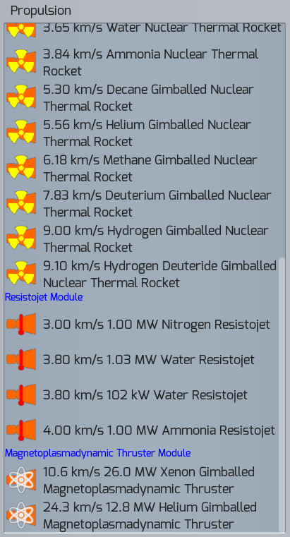
After implementing the Nuclear Thermal Rocket, I looked into ion thrusters, and settled on the Magnetoplasmadynamic (MPD) Thruster, because it had some of the highest thrust out of all of them, and thrust is quite nice for dodging in combat. I built a few thrusters in the megawatt range, tried them out on a few missions, and their limitations became immediately apparent.
Thrust, and by extension, acceleration, is not simply important for dodging in combat. Low accelerations not only prevent you from using standard orbital maneuvers like Hohmann Transfers or Orbit Phasing, they vastly increase burn time and ultimately travel time. Getting between planets, for instance, might require a longer burn time than the actual period of the planets themselves, years, or even decades! Getting cargo anywhere in the solar system was prohibitively slow. NTRs and chemical propulsion turned out to be far superior.

With combat spacecraft, it only got worse. The accelerations are so poor that orbital evasion maneuvers are impossible to execute against high-g missiles or anything else really. In range of weapons fire, enemy projectile range is limited primarily by the target’s areal cross section, and its acceleration. With accelerations as low as the MPD Thruster was yielding (micro-g’s at best, nano-g’s at worst), my warships were basically immobile, sitting ducks for the enemy. And I should emphasize: The MPD Thruster yields one of the highest thrusts of any of the ion drive designs.
Okay, though we can just crank up the power consumption, and get higher thrusts, right? You can actually, as long as you keep an eye on the various stresses of the design. In particular, Onset Phenomenon of MPD Thrusters gets rather nasty at megawatt levels of power.

But more power requires more nuclear reactors, and more reactors require more heat radiators. The amount of heat radiators by mass became overwhelming, and reduced the spacecraft’s overall acceleration faster than adding more MPD Thrusters could increase it.
At this point, the Rocket Power equation (it’s further down in the link) should be pointed out. For a given amount of power, the thrust is inversely proportional to the exhaust velocity. This equation became very evident with MPD Thrusters. One could increase the mass flow of the engine (and thus, the thrust) at the cost of plasma excitation (and thus, exhaust velocity). The two quantities were directly opposed.
I designed a MPD Thruster with exhaust velocities comparable to NTRs, and found the thrust still lacking. NTRs had a rocket power in the multi-gigawatt range, and my MPD Thrusters were in the tens or hundreds of megawatts range. They’re both run via nuclear reactors, so why were MPD Thrusters so much worse in this regard?
It wasn’t until I designed resistojets powered by a nuclear reactor (Nuclear Electric Propulsion) that it hit me. The additional step between the nuclear power generation and actually utilizing this power is the problem. NTRs and Combustion Rockets expel most of their waste heat through the exhaust itself, while nuclear powered resistojets and MPD Thrusters must expel most of their their waste heat through heat radiators unconnected to the drive. Making a MPD Thruster or resistojet with the same power as NTRs requires a staggering amount of radiators while NTRs do not. Counting the mass of the radiators needed for such a high powered MPD Thruster into the drive’s total thrust-to-mass ratio yields abysmal ratios.
In fact, most drives suffer from this same limitation that NTRs and Combustion Rockets avoid. Only a few drives, like Nuclear Pulse Propulsion manage to sidestep the issue of requiring enormous amounts of radiators to have comparable power. But ion drives, and nearly all other high-exhaust-velocity counterparts, fall flat. As it turns out, thrust is hugely important to spacecraft.
It was at this point when it finally clicked for me why aerospace engineer Robert Zubrin, inventor of the Nuclear Salt Water Rocket, has long since called ion thrusters (in particular, VASIMR) a hoax. I personally wouldn’t call them hoaxes, but in order for them to be the future of space travel would require a hypothetical advance in technology to fix their glaring flaws. As it stands, ion thrusters don’t appear to be viable for any sort of bulk space transportation. For scouts and tiny probe spacecrafts, ion thrusters are great. But for moving cargo, passengers, and military ordnance around the solar systems, ion thrusters and electric propulsion simply aren’t going to cut it.

Extremely high thrust propulsion looks to be the way to go, unless the radiator limitations can be solved somehow. Discounting far future drives like antimatter engines, this cleanly kills off a huge portion of potential drives for bulk space travel: ion thrusters, most sails and tethers, electric thrusters, photon thrusters, fission fragment thrusters. All you are left with besides chemical propulsion is nuclear, nuclear, nuclear. Maybe I should’ve listened to Robert Zubrin from the start.
That’s a quick run through on the rocketry of the game, next time we’ll explore one of the most overlooked, yet extremely important parts about space travel: the propellant tanks themselves, as well as the pros and cons of different propellants to use. As it turns out, neither of these are as simply as you might imagine.

I find the comparison between electric and nuclear thermal engines rather un-fair.
For one, you should be comparing engines of equal power output. Second, they should be designed towards a deltaV objective. The main advantage of having high exhaust velocity is that you need proportionally less propellant mass.
Here’s a 1GW Nuclear thermal engine with 7km/s exhaust velocity, designed for giving a 100 ton dry mass spaceship 20km/s and 5 km/s mission deltaV:
1GW
Efficiency: 0.7
Waste Heat: 300MW
Radiators: Two radiators of 15x30m at 1300K
Radiator mass: 34kg/m^2 (microtubule array) – 30.6tons
Thrust: 200kN
Dry mass with radiators: 130.6tons
Total mass: 1632ton for 20km/s, 246ton for 5km/s
Average acceleration: 0.82m/s^2, 1.17m/s^2
Here’s a 1GW MPD thruster with 20km/s exhaust velocity, with the same deltaV objective:
1GW
Efficiency: 0.5
Waste Heat: 500MW
Radiators: Two radiators of 25x30m at 1300K
Radiator mass: 34kg/m^2 (microtubule array) – 51 tons
Thrust: 50kN
Dry mass with radiators: 151tons
Total mass: 365tons for 20km/s, 188tons for 5km/s
Average acceleration: 0.23m/s^2, 0/29m/s^2
So on equal terms, for similar missions, the nuclear-electric drive only accelerates three to four times less than a nuclear thermal drive. It requires better cooling, but will overall easier to rotate and aim.
This comparison disregards armor and propellant tank volume, both of which work in dis-favor of the massively heavy nuclear thermal drive. Nuclear electric has a final advantage in power supply – while a nuclear thermal engine has to extract electricity through inefficient thermocouples or other waste-heat derived extraction methods, a nuclear electric drive just has to redirect the power generated by the nuclear reactor.
LikeLike
I do mention scaling up the power of the MPD Thruster to the same gigawatt levels as the NTR, and the tremendous amounts of radiator mass that it adds.
As for the systems you’ve listed, you can’t simply come up with numbers that ‘seem’ correct and say they work. Can you give me a detailed breakdown of how these systems are composed? What sort of mechanical or thermal analysis have you done on these systems? How is the heat cycle set up?
Just doing some quick napkin math, your MPD Thruster’s reactor requires a 2600 K peak temperature in order to achieve that sort of efficiency, and that’s assuming the entire reactor uses a Carnot Cycle and is isentropic, which it won’t be. In practice, entropic losses will drive that temperature far above. But for now, let’s assume an idealized Carnot Cycle. You’ve got a 1300 K temperature drop across the power converter which will likely reach multi-gigapascals of thermal stress, and your power converter also needs to have a melting point above 2600 K.
And that’s assuming a Carnot Cycle. You won’t have that in real life. Your actual reactor will require a much higher peak temperature in order to achieve those sorts of efficiencies, likely around 3000 K, which is getting even further from reality.
Can you give me a breakdown of the materials used, and a layout of the coolant cycle(s) used for your designs? More detail on your radiators would be needed as well, as your radiator efficiency percent doesn’t seem to be listed, nor any mention of its derivation. Right now, all you’ve given me is a series of attributes coming from a black box. I could also dream up a design with 99% efficiency and a coolant outflow temperature of 3000 K, and say ‘oh it just works, it’s a black box’. Unless each system is very rigorously evaluated in terms of all thermal and mechanical stresses, it doesn’t really mean anything. Science doesn’t really work like that, you can’t simply come up black boxes and say they work.
If you need help making your designs more scientifically rigorous, I absolutely recommend DOE Fundamentals Handbook: Nuclear Physics and Reactor Theory (both Volumes 1 and 2). That was the primary book I used for implementing my simulation’s nuclear reactors. For getting your radiators correct, Spacecraft Thermal Control Handbook, Volume 1: Fundamental Technologies was my go to textbook. If you have difficulty acquiring either, I can send you a pdf of either, just let me know.
LikeLiked by 1 person
I didn’t go for number that seem correct, I worked them out using mathematical equations.
Radiator surface area (and mass) scale up linearly with the amount of waste heat to be removed, but falls by the power ^4 with the radiating temperature. This means that the only real upper limit is the temperature the radiator can handle, as lowered efficiency due to a smaller temperature difference between reactor core and coolant fluid can be compensated by the increased radiator temperature.
The nuclear core temperature I assumed was a minimum of 2600K (http://sbir.nasa.gov/printpdf/54860) to 2800K (http://ntrs.nasa.gov/archive/nasa/casi.ntrs.nasa.gov/20120003776.pdf).
I did not put in as much effort as you did in designing the systems I used for my example, because I was only illustrating the point that when compared on an equal output, for fair comparison, the acceleration levels of the spacecraft were not so far apart.
For the heat exchanger, tungsten can support about 3600K temperatures and can suffer stresses of hundreds of Giga-pascals.
The radiator comes from this design on Atomic Rockets: http://www.projectrho.com/public_html/rocket/basicdesign.php#id–Heat_Radiators–Radiator_Types–Microtube_Array
It was designed in 1990, and modern materials (let alone futuristic) will improve both its heat capacity and mass per square meter, but I used the original figures.
Black boxes are useful when trying to simplify the dozens of systems on a spaceship to comparable elements. It’s real life that doesn’t work like that, not the underlying maths.
LikeLike
Both of the links you sent me were about NTRs, not nuclear electric. NTRs can absolutely achieve 3000 K or greater, that’s one of the reasons why NTRs are so much better than nuclear electric MPDs, and that is more or less exactly what my blog post is about.
Radiator efficiency is not merely limited by temperature, that’s a misconception. The dimensions of the radiator, material used, coolant used, and temperature all contribute to an efficiency factor that is very plainly detailed in Chapter 8 of Spacecraft Thermal Control Handbook, Volume 1: Fundamental Technologies. Would you like a pdf, I can email it to you? I found it to be a very good read on the subject.
LikeLike
Whoops, meant Chapter 6, Section 7 of the textbook titled “Radiator Effectiveness”. Equation (6.5) to be specific.
LikeLike
So, basically, to make something like this work, you would need to use technologies and methods that have never been empirically tested and so might not even work or might have bad drawbacks. Droplet radiators, direct conversion fusion electric power, that sort of thing.
What was your thought on rejecting droplet radiators? They do massively increase performance from the numbers I’ve seen (radiator mass versus heat rejection)…
LikeLike
Droplet radiators have a significant issue that if you accelerate at all while they are in use, the droplets are going to miss the collector and get scattered into space. This means you can’t dodge while they are in use, and any major impact on your craft will similarly scatter the droplets into space. Not only that, a nuclear detonation nearby could possibly evaporate your droplets and ruin it rather easily.
The only way to get around this issue is to shut off the radiators during combat, which is nigh impossible at the power levels in use. You’d need enormous heat sinks to store off your heat during combat, which easily will exceed the mass of your entire ship.
Alternatively, you could wrap the droplets in a optically transparent sheath, but at that point, why not just return to standard radiators?
LikeLike
Specifically, you say that the only limit on droplet radiators is boiling point. Obviously this isn’t the only limit – you don’t have to use liquid tungsten droplets (although the performance would theoretically be amazing, considered in isolation) The paper I saw on it used liquid tin, which happens to have very low vapor pressure at 1000 kelvin.
At 1000 kelvin you have relative low emissivity per area but you have absolutely amazing mass efficiency. You’re spreading just a few kilograms of total tin across a vast area. Want to vent 500 megawatts at 1000 Kelvin? That’s just 5×10 meters. Most of the mass is in the 5 meter long booms at each end that contain the nanoscale spray nozzles and collectors, the coolant itself is negligible. You’re talking 1 ton of radiator mass, tops…
LikeLike
Well, for mid-combat dodging, you actually only want to make maneuvers in a plane perpendicular to the line of fire from the enemy kinetic weaponry. Use 3 collection booms instead of 1. Spins along that plane will send the droplets into the 2 side booms.
Draw a picture. It’ll work. The coolant actually in the droplet sheet is only a small percentage of the total coolant in the system so a nuke won’t end the battle.
And with orders of magnitude better radiator performance, this changes many of the _other_ assumptions.
This is why when I looked at writing a game like this myself, I decided early on you’d have to make it fully modular, using a GUI interface similar to Minecraft, for maximum flexibility. Too many things like this where if you change one assumption everything else changes. The game would then need an “assumptions” file that has numerical constants for the assumptions in a particular instance of the game “universe”, where those variables vary from measured, today values to reasonable extrapolations of what is doable. Rolling a new game randomizes the file, or you could set it normally. You then derive the stats of everything from these assumptions procedurally.
LikeLike
If you wish to send me links on the engineering whitepapers or textbooks detailing your technology, please do and I’ll gladly look into them.
If you are inventing technologies of your own, please post a detailed spec of a sample use case including a full layout with dimensions, materials used for each section, and detail of the entire coolant pipeline within, including pressure. Also needed is a detailed analysis of all stress and limitations of all sections of this technology.
Best of luck on your game.
LikeLike
Do we get to play around with nuclear saltwater rockets? There’s just something appealing about strapping yourself and some weapons to the Devil’s Own Flamethrower and riding to war.
LikeLiked by 1 person
Hey qswitched, I would definitely be up for a pdf if it’s going.
LikeLike
Absolutely, just sent you both textbooks by email!
LikeLike
qswitched : my “triple collection boom” proposal is more like taking something that is well established, with the studies done on it, and saying “mount it perpendicular”. It’s not very complicated and any competent engineer can just see how to do it. If the forward emission boom for the droplet radiator is ahead of the direction of thrust, such that the droplets “fall” towards the rear boom, side booms are just booms to the left and right of that. You can just see if you draw it on a napkin that rotations within the plane described by the 4 points of the rectangle inscribed by the booms will tend to “push” the droplets into the side booms. This is a blindingly obvious innovation so you can maneuver with the radiators running. You must position your ship so the evasive maneuvers are within this plane, however.
A high speed close range pass could result in rapid angular change and prevent you from being able to evade fire when this happens, however, at close ranges in space combat lasers are basically instantly lethal so that probably wouldn’t happen.
Stresses? If the booms are made of metal and the ship can’t exceed 1 G you can just ignore that – a few kilograms of coolant slapping the side booms is negligible.
Impact velocity with the collection boom? Obviously you turn down the pressures on your coolant pump manifold when you begin to maneuver or make the collection booms slightly more durable.
You’re being pedantic. I’m not making any more assumptions than you are when you take semi-tested modular subsystems for a warship and “bolt them together in space” and assume it will work as a warship. In the real world this won’t actually work, you would have to do decades of engineering first to integrate something this complex. However, ultimately, since the math checks out, you would ultimately end up with a vehicle with roughly the performance you modeled on paper. There would be all kinds of subtle deratings, though, like having to use heavier than expected metallurgy around that reactor spewing out the neutrons or not having quite the predicted accuracy on your weapons when they are on a ship that is maneuvering and vibrating.
You can use hundreds of NASA papers as a source, you’ve obviously already researched this.
I’m not working on my own game, I’m pointing out that the software engineering solution to let you do this easily would be if you had defined radiators as flat textured plate with some code modeling them as a system, you could introduce droplet radiators as a special type of regular radiators with the collision physics for the plane handled differently. I suspect the actual reason you’re being so intransigent is you probably invested a lot of time developing a model you thought was optimal, and you sorta cemented yourself in code-wise to that model being correct.
LikeLike
I believe you have misunderstood the depth of complexity of my simulation. I’ll present you with a sample radiator system used in my simulation (25.3 t Silicon Carbide Radiator).
Given Attributes
Height = 5.52 m
Width = 4.00 m
Thickness = .10 m
External Thickness = .025 m
Composition = Silicon Carbide
Surface Finish = Molybdenum
Derived Attributes
Heat Pipes per Panel = 40
Heat Pipe Spacing = .0976 m
n = Index of Refraction
k = Extinction Coefficient
Absorption Coefficient (m^-1) = 4 * Pi * k / Wavelength (m)
Photon Opaque Percentage ~= 99% (chosen as being reasonably opaque)
Surface Finish Thickness = -log(Photon Opaque Percentage) / Absorption Coefficient
Reflectance = ((1 – n)^2 + k^2) / ((1 + n)^2 + k^2)
Emissivity = Absorptivity = 1 – Reflectance (per wavelength)
Zeta = Stefan-Boltzmann Constant(W/m^2/K^4) * (Heat Pipe Spacing(m) / 2)^2 * (1 + (External Thickness(m) / Thickness(m)) * (InletTemperature(K))^3 * Surface Finish Emissivity * 2 / (Panel Thermal Conductivity(W/m/K) * Thickness (m)
= .01 @ 1000 K
= .0276 @ 1500 K
Efficiency = 1 – 1.125 * Zeta + 1.60 * Zeta^2 Zeta = .2
= .9889 @ 1000 K
= .9701 @ 1500 K
Panel Mass = 5064.87 kg
Surface Finish Mass = .000767 kg
These equations require the Density and Thermal Conductivity of Silicon Carbide, let me know if you have trouble finding numbers for them. It also requires density of Molybdenum, and the Refractive Index spectra of Molybdenum. I’m using a huge amount of data for these spectra (as it varies wildly per wavelength), and you can find much of it at http://refractiveindex.info/?shelf=main&book=Mo&page=Ordal
You’ll note my efficiencies are quite high (95% or better). This is because I spent a lot of time minmaxing the equations in order to achieve these sorts of results, although the efficiencies suffer at temperatures outside of what I’ve optimized for.
Now it’s hooked up to a 13.0 MW Nd:YAG Laser, and so we have a complete coolant loop between the laser and the radiator.
Coolant = Hydrogen
Coolant Inlet Temperature = 1234.915 K
Waste Heat = 12.4067 MW
Let me know if you want details on how these values were derived. They came from the laser side of the equations, and they’re a whole other beast.
Finally, we have a Turbocompressor which is going to be pumping this coolant loop.
Given Attributes
Material = Martensitic Stainless Steel
Rotation Speed = 440.5 RPM
Pump Radius = .410 m
Hub Radius = .082 m
Blade Thickness = .001 m
Derived Attributes
Absolute Inlet Angle = .524 radians
Blade Centripetal Acceleration (m/s^2) = RotationSpeed (radians/s) * Pump Radius (m) = 872.434 m/s^2
(Note there’s a ton of steps between centripetal acceleration and inlet normal velocity, let me know if you want that fully enumerated)
Turbopump Inlet Normal Velocity = 4.9137 m/s
Volume Flow Rate = Inlet Normal Velocity * 2.4899 m^3/s
Mass Flow Rate = Volume Flow Rate * Fluid Density = 176.41 kg/s
Blade Mass = (Blade Volume (m^3) + Shell Volume (m^3) + Hub Volume (m^3)) * Blade Density (kg/m^3) = 18.08 kg/m^3
Blade Stress = Blade Centripetal Acceleration (m/s^2) * Blade Mass (kg) / Blade Cross Sectional Area (m^2) = 64.123416 MPa
Hub Stress = Mass Flow Rate (kg/s) * Outlet Normal Velocity (m/s) / Hub Surface Area (m^2) = 2564.7 Pa
Specific Enthalpy Increase = Mechanical Work (J) / Mass Flow Rate (kg/s) = 64.386 J/kg
Temperature Jump Across Turbopump = Specific Enthalpy Increase (J/kg) / Fluid Specific Heat (J/kg/K) = .0045 K
Thermal Expansion Stress = Young’s Modulus (Pa) * Thermal Expansion Coefficient (K^-1) * Temperature Jump (K) = 10438.5 Pa
You’ll need data on the densities of the materials used, but also data on the Martensitic Stainless Steel’s Yield Strength, Young’s Modulus, Thermal Expansion Coefficient, all of which can be found online. Looking at one in particular, the yield strength of this material is 1.9 GPa, which is far in excess of any of the stresses calculated. All such stresses in this particular system are easily dealt with, because the coolant system of an arclamp pumped laser is actually quite simple. Other systems have much more difficult tolerances to deal with.
A lot of steps have been skipped for clarity, however, I’m happy to provide more in case you need it. As you can see, this is the depth of simulation that is expected of all technologies in order for them to exist in my simulation. If a technology can’t satisfy this sort of rigor, I won’t be implementing it in my game.
When you get your hands on my simulation, I’m sure you’ll be very eager to experiment with the values in trying to develop your own ideal systems. I also encourage you to point out any errors in my equations, it’s always helpful for me to have others double check my work.
Finally, I again definitely recommend several textbooks. The Spacecraft Thermal Control Handbook covers everything radiators and more, and I found it be a very fun and interesting read. The Handbook of Turbomachinery is another excellent read. Let me know if you would like pdfs of either.
LikeLike
Well, qswitched, that’s an interesting simulation. However, from what I know about such things, I don’t think a more detailed simulation like you describe is necessarily more correct.
See, your sim depends now on hundreds of internal steps. A faulty assumption or bug, and the outcome is wrong. Furthermore, many of these models you are using don’t reflect the reality of real world engineering.
I personally think you would be better served by saying : “ok, what is the performance of the closest real world equivalent? Let’s just assume they made it lighter for space”.
I know that sounds less accurate but in practice it will be vastly more correct. A simpler model is more accurate because your simulation is multiplying many stages of coefficients and thus is vulnerable to accumulated error.
LikeLike
However, with all that said, I do think this is an interesting approach. I was implicitly assuming you were thinking along the same lines I was, in making a game form similar to existing games in terms of control and gameplay. What I was thinking was you would have modular subsystems, which are assumed to be engineered to the limits possible for whatever they are, and you only have subsystems in the game that have a use.
So instead of 50 different kinds of possible engine, there’s just hydrox and a single kind of optimized NERVA and methane/ox. The others don’t really make sense, there’s not enough fluorine in the solar system to practically use it as propellant, for example.
Player just picks the subsystem and can basically only choose it’s scale. They click it down. Autoroute the wiring – are you modeling wiring and piping mass for differential placement of subsystems?
Rinse and repeat til they have a vehicle, then they fly it, similar lines to what you have in that computer is in direct control for most maneuvers.
You’ve added a minigame of optimizing for optimal engineering performance. Sort of interesting, although as I said, I do not think this would actually be scientifically as accurate as you think because your models are too complex and yet probably still neglect all kinds of subtle factors.
LikeLike
Thought of an even better way : http://ntrs.nasa.gov/archive/nasa/casi.ntrs.nasa.gov/19870010920.pdf , page 19.
Using a single centrifugal collector LDR. See how all the droplets converge on a single collection boom? As the ship undergoes accelerations, the droplets will all undergo identical relative movements (technically they aren’t accelerating, the ship is).
So you mount the collector on a servo arm and have it move around to catch the droplets. They will always remain converged, the acceleration of the ship just means that where the intersection point is changes.
This is a straightforward control system readily doable with state of the art. Like everything, you could get a terrestrial prototype sorta working for a few thousand bucks, but a space rated fully baked version would cost billions.
You would be able to accelerate any way you want. Limiting factor is the grab region of the collection arm – you can easily work out from the velocity of the droplet stream and the rate of acceleration what your exact limits are.
LikeLike
Oh, using the chart on page 24 : I choose liquid aluminum at 1040 kelvin. 17 kg/kilowatt, 30 metric ton radiator system. Using supercaps and high end servos, let’s budget a generous 1 ton for the servo driven robot arm that the collector cup is mounted to (it moves in 3 dimensions – as you accelerate “forward” the droplet intersection point will shift backwards, etc). Boom, baby. 31 metric tons using conservative assumptions. 1040 kelvin is also relative “cold” which means more efficiency which means more power output which means bigger lasers which means…
LikeLike
These are essentially Torch ships, right? As such, isn’t the exhaust itself usable as an offensive and defensive weapon vs enemy ships and incoming missiles? If the computer is handling the drive, nav and combat control, it could work out the intercepts? So we could choose from a menu of pre-programmed series of ship’s responses if certain ranges were crossed.
Has anyone tested the angled armor theory? Most ships in the demp were taking hits from the side. The point of the taper to the hul is to improve the armor’s effectiveness due to the angle. Seems a thick armor nosecone with a hugher angle to it would be a good ace to show incoming everything. small profile and improved armor… The computer could work out direct facing angles similar to above? Of course then you are closing range, so this tactical choice may not be right for every situation.
Any use of neutral particle excellerators in this simulator? Would make a great weapon for firing right through most armor and frying the crew and electronics.
LikeLike
These are not torch ships, actually. Torch ships use very far future rocket technology, and Children of a Dead Earth remains very near future, using only technology that has been heavily studied.
This post has info about what the computer handles during combat: https://childrenofadeadearth.wordpress.com/2016/04/29/misconceptions-about-space-warfare/
Sloped armor has been studied a lot and is in use by modern tanks today: https://en.wikipedia.org/wiki/Sloped_armour
LikeLike
Here’s one scenario where mpd thrusters might be viable on a warship: consider ships that already have a very powerful laser and all the associated equipment. if you already have the massive radiators and powerful reactor for your laser you might as well use them out of combat too, and those thrusters seem to be pretty lightweight. Retain the NTR, and use the MPD to help it during long voyages…
LikeLike
A big issue with MPD thrusters that remains with long voyages is travel time. While it would help the delta-v immensely, low thrust causes travel time increases significantly.
For civilian operations, this might not be a problem, but in warfare, time is generally an important consideration. For instance, if your enemy can reach an objective in 6 months while it takes you 18 months, it probably won’t be worth the delta-v savings you get.
LikeLike
I really admire the way you handle these questions. I imagine this subject attracts a fair number of cranks and armchair engineers. The level of detail incorporated beneath the surface of the simulation is both astonishing and gratifying.
Maybe a farther-future sequel could contain Torchships with NSWR propulsion, with somewhat less exacting engineering details (since many of them would be unknown).
See, I’m such a typical gamer: Willing to trade off accuracy just to have a cool engine 😉
LikeLiked by 1 person
You forgot few things.
MPD thrusters can be cooled regeneratively, and should be. This will allow higher mass flows, and reduce the energy needed to ionize the propellant.
As you have a reactor on board, you will also want to use it to preheat the propellant. This also removes the need to have much bigger radiators to accomodate heat flows from reactors when they work on peak power.
Moreover, ionization energy can be further lowered by adding a low power rf source and adding some caesium vapour to the propellant. This will allow to convert up arround 30-40% of electricity into accelerating the propellant with lorentz force depending on engine geometry.
At some point, as the engine and voltages grow bigger, there will be less, and less benefit of additionally accelerating plasma with mhd. MPDs top thrust is limited by geometry. At scales above break-even point imposed by geometry, a simple arcjet will become a better solution.
Passive black body radiators are not mass efficient. What is already in the lab are anti-stokes scattering radiators – the so called plasmon pumps, and gas dynamic lasets. They can dissipate from 2 to 4 times the energy they need to operate themselves.
LikeLike
Could an NTR be made better by use of fusion instead of fission? Fusion gets you more energy than fission does, but I know another limiting factor is the temperature that can be reached without melting parts.
I know this is beyond the scope of this game, given as it isn’t a technology which has been demonstrated to work.
LikeLike
So efficiency is the limite to MPD thrusters does this mean that high efficiency reactors like fission fragment reactor (about 95% efficient) can make MPD useful.
If yes then i would go for it, you anyways need a lot of power in combact, might as well use it for propulsion. Also high efficiency means less readiators, and MPDs and FF reactor are much easier to mentain.
And any MPD will likely use some dence gas (xenon) which need much smaller tanks (less surfact area to armore)
If we need more thrust why cant we just add a afterburner. Just dump some extra gas in the exaust right before it was leaving and you get thrust equal to high end NTRs.
LikeLike
It seems to me like you exaggerate travel time increases (at least for interplanetary trajectories). Running GMAT I find that you can get a low thrust engine vehicle to C3 = 12.2 (the same as MAVEN outbound from Earth on a trajectory to Mars) in less than 60 days from LEO, at a distance of 9.94 million kilometers from Earth at C3 = 12.2. MAVEN took a couple months less than a year to get to Mars, so you can expect a little longer total time thanks to the lower acceleration. Make it a year and a few months. Certainly longer than what a nuclear engine would do on average but nothing a cargo carrying vehicle would really have an issue with, especially if the cargo carrier is unmanned. And that’s assuming we start in LEO. There’s really no reason to do so, as chemical and nuclear engines are better suited for gravity wells. Starting at a higher orbit would reduce the time to C3 = 12.2 and greatly reduce wet mass for the mission given a specific dry mass.
Now, InSight had a C3 of 14.3. Running the same GMAT sim (again from LEO) still shows less than 60 days of acceleration at 10.87 million kilometers from Earth once that C3 is reached. InSight got to Mars in 6 months and 21 days. Once again it’ll take time to slow down at Mars so maybe 9 to 10 months. Again, we started in LEO, so it could be made much quicker if we start at an orbit closer to C3 = 0.
It really seems to me like low thrust vehicles would be the best option for cargo. In the inner system solar power works well and the outer system would require reactors.
Combat is a different story altogether, and travel deeper in a gravity well – such as between the inner moons of Jupiter or in LEO – would definitely be served better by chemical or nuclear.
But it seems like interplanetary trajectories (and even to an extent trajectories starting at low orbits) may actually be practical with low thrust engines. Dawn took roughly two years to transit from Vesta to Ceres, which roughly corresponds to a standard impulse transfer between the two bodies, even though it used ion engines.
Definitely seems like they would be in use, at least commercially. Maybe even for logistics as well.
And of course there are hybrid vessels. Using two propulsion systems. That probably isn’t likely but it may be preferable in some cases – logistics vehicles for example, specifically tankers where minimizing the warship propellant used by the tanker would be an important design criteria.
I ran GMAT with the following assumptions:
Dry mass: 850 kg
Prop mass: 756 kg
Isp: 4200 seconds
Thrust (constant): 5 N
Of course the simulation granularity wasn’t high, but the trajectories are possible.
LikeLike
Hi qswitched
I see no one asked this (perhaps because it’s a stupid question?) but if ion thrusters have better exhaust velocity and rockets have better thrust couldn’t you put both on the ship, each specialized to only do the thing it’s best at? Would you need such a huge ion engine if it was only used after the thrust phase?
LikeLike
Not a stupid question. Hybrid propulsion has been a feature of many NASA mission proposals, and you will find many designs in the COADE forums featuring both nuclear thermal and magneto-plasma-dynamic (electric) engines.
LikeLike